Tibbo > Hardware > Outdoor Sensor System
Outdoor Sensor System (OSS)
Built for Tough Environments
Outdoor Sensor System (OSS) is a line of wireless sensor products.
Capitalizing on decades of our experience designing high-reliability electronics for demanding environments,
the OSS was engineered to withstand harsh weather conditions continuously.
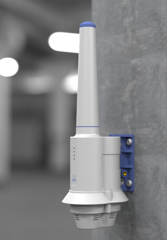
Surface or Pole Mounting
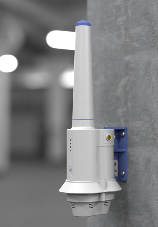
Attach your OSS device to a flat surface using the included bracket.
This method is ideal for mounting OSS devices on internal and external walls, beams, and other flat surfaces.
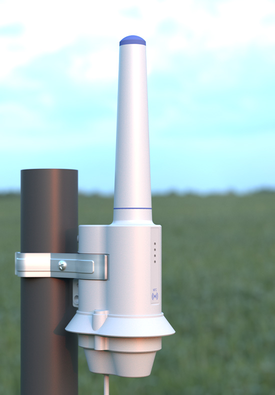
Mount OSS devices on standard 5cm (2") pipes using the included metal lips.
This option is great for agricultural applications that require external sensors for soil measurements.
Attach your OSS device to a flat surface using the included bracket.
This method is ideal for mounting OSS devices on internal and external walls, beams, and other flat surfaces.
Mount OSS devices on standard 5cm (2") pipes using the included metal lips.
This option is great for agricultural applications that require external sensors for soil measurements.
Onboard or External Sensors
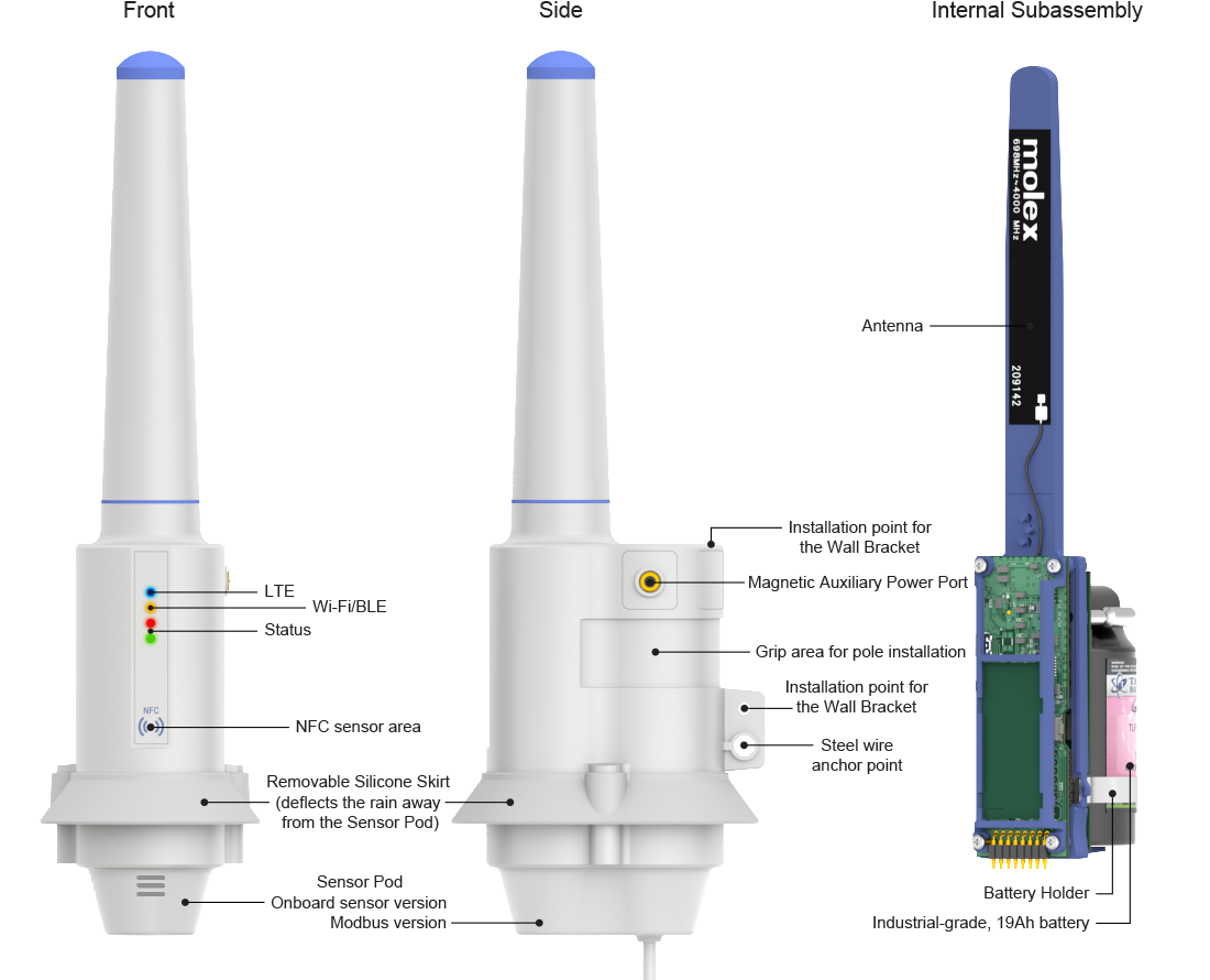
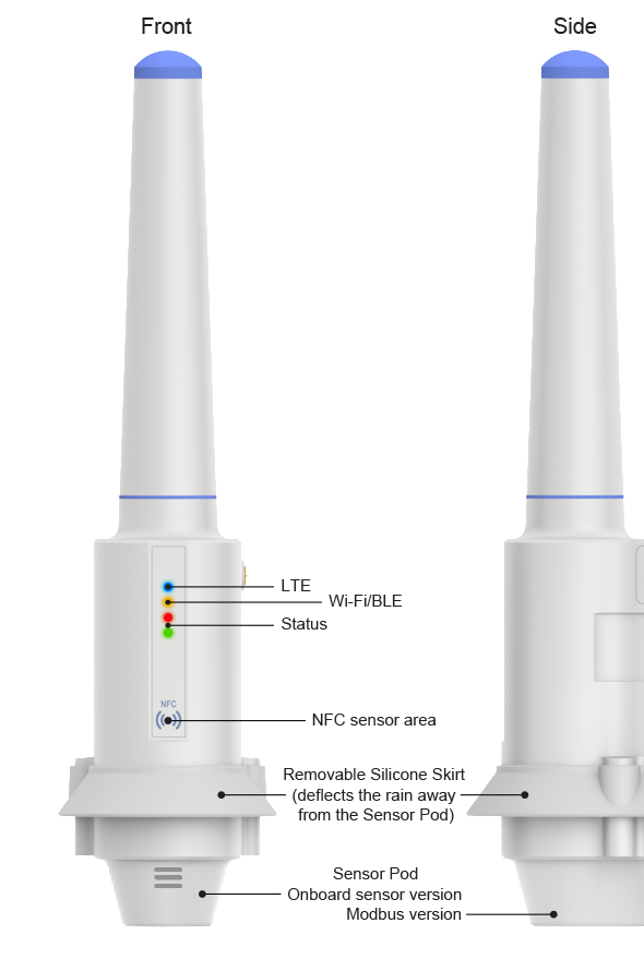
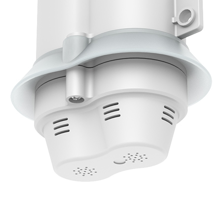
Housed inside the Sensor Pod, onboard sensors facilitate monitoring of various environmental parameters, such as
temperature, humidity, CO2, PPM, and others.
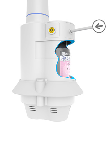
Sensor Pods feature ventilation holes, enabling air to flow over the sensors.
An internal partition hermetically insulates the rest of the device from the sensor compartment.
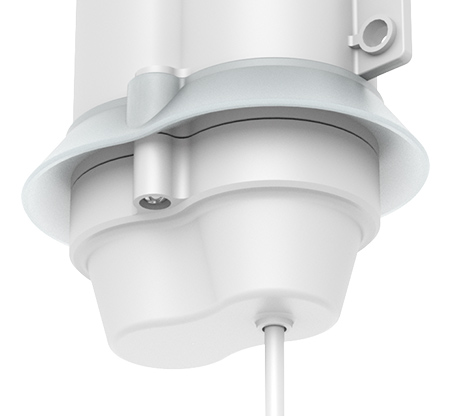
The Modbus Pod connects your OSS device to external Modbus sensors.
This option facilitates the use of external probes to measure the parameters of
soil, water, air, wind, rainfall, or sunlight.
Modbus support makes OSS devices compatible with a myriad of industry-specific sensors.
The attached Modbus cable is rodent-resistant and enters the device through a watertight gland.
Housed inside the Sensor Pod, onboard sensors facilitate monitoring of various environmental parameters, such as
temperature, humidity, CO2, PPM, and others.
Sensor Pods feature ventilation holes, enabling air to flow over the sensors.
An internal partition hermetically insulates the rest of the device from the sensor compartment.
The Modbus Pod connects your OSS device to external Modbus sensors.
This option facilitates the use of external probes to measure the parameters of
soil, water, air, wind, rainfall, or sunlight.
Modbus support makes OSS devices compatible with a myriad of industry-specific sensors.
The attached Modbus cable is rodent-resistant and enters the device through a watertight gland.
Flexible Powering Options
Battery Power
OSS devices are optimized for battery power and may provide up to three years of operation on a single battery.
When equipped with a battery and onboard sensors, an OSS device is fully self-contained and requires no external connections.
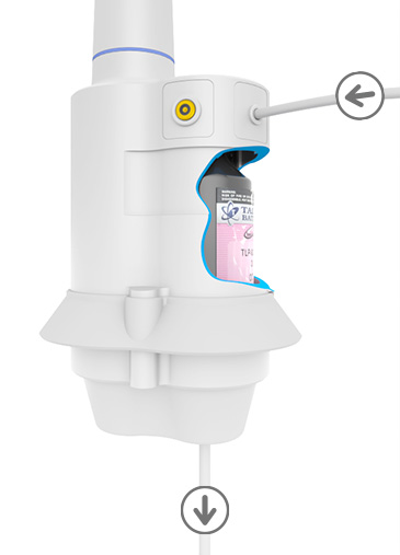
Line Power
Alternatively, power may be supplied externally through a rodent-resistant power cable connecting to the side of the device.
OSS may be ordered with an onboard battery, line power, or both.
Powering Modbus Sensors
OSS models with Modbus pods can power attached sensors.
The power is sent through the same "bottom" cable carrying the Modbus signals.
OSS conserves the battery by powering external sensors only when it's time to take the readings.
Powering From Modbus Sensors
In a reversal of the roles, OSS devices may be powered by an external Modbus sensor.
This is similar to using the side (line) power, except that the power to the OSS is supplied through the Modbus cable.
Flexible Powering Options
Powering From Modbus Sensors
In a reversal of the roles, OSS devices may be powered by an external Modbus sensor.
This is similar to using the side (line) power, except that the power to the OSS is supplied through the Modbus cable.
Line Power
Alternatively, power may be supplied externally through a rodent-resistant power cable connecting to the side of the device.
OSS may be ordered with an onboard battery, line power, or both.
Battery Power
OSS devices are optimized for battery power and may provide up to three years of operation on a single battery.
When equipped with a battery and onboard sensors, an OSS device is fully self-contained and requires no external connections.
Powering Modbus Sensors
OSS models with Modbus pods can power attached sensors.
The power is sent through the same "bottom" cable carrying the Modbus signals.
OSS conserves the battery by powering external sensors only when it's time to take the readings.
Internal battery and line power
Powering external sensor(s)
Powering from an external sensor
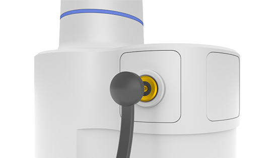
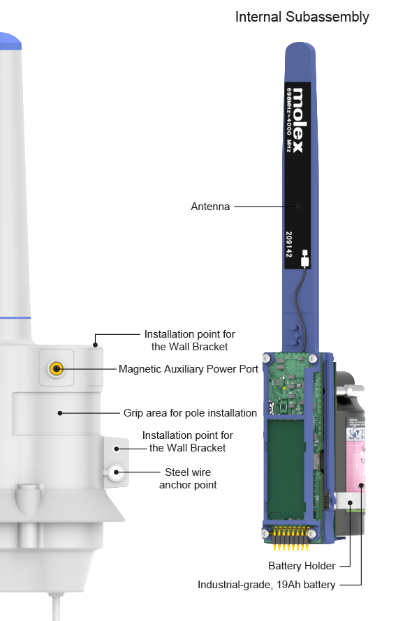
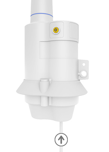
Auxiliary Power Port
What if an OSS unit requires management, but its internal battery is depleted,
and no other power source is available?
Bring the device back to life with a USB power bank!
The included USB power cable is equipped with a magnetic connector that attaches
to an auxiliary power socket on the side of an OSS device.
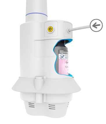
Maintenance-in-Place
The OSS has been designed to simplify the on-site device maintenance and repairs:
Remove the Sensor Pod.
Slide out the internal subassembly.
Replace the battery or the entire subassembly.
Slide the subassembly back in.
Reattach the Sensor Pod.
Done, all without dismantling the device or disconnecting external wires.
Cloud Uplink Options
OSS devices securely send collected sensor data to the cloud.
Initially compatible with Microsoft Azure IoT Hub,
OSS may be adapted to virtually any public or private cloud service.
The product supports two-way cloud communications, enabling data uploads and remote management of OSS devices,
including the over-the-air (OTA) firmware upgrades from the cloud.
Wi-Fi Only Version
Available immediately, Wi-Fi-only ("W") OSS models are great for installation inside and outside buildings,
greenhouses, grow rooms, and other facilities with Wi-Fi coverage.
Wi-Fi + LTE Version
Supporting Cat-M1 and NB-IoT LTE, Wi-Fi/4G ("W"+"C") devices can be installed virtually anywhere.
Great for deployments across vast urban areas, farm fields, and forests,
these models facilitate the creation of large-scale distributed sensor networks.
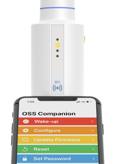
NFC and Bluetooth for On-Site Management
Physical security is paramount to any sensor deployed in an outdoor area.
OSS devices have no exposed buttons to prevent unauthorized access.
All close-range interactions with an OSS unit require NFC authentication using the
OSS Companion App.
The App:
- Provides NFC authentication and password management
- Enables device configuration via Bluetooth Low Energy (BLE)
- Supports on-site over-the-air (OTA) firmware updates via BLE
Specifications
- Processing unit and storage
- ARM Contex-M4 architecture + Wi-Fi 802.11a/b/g/n + BT4.2
- 192MHz clock frequency in active mode
- Powered by Tibbo OS (TiOS)
- Stores up to two compiled Tibbo BASIC/C binaries (apps)1
- APP0 is for system-level configuration
- APP1 is the main OSS application
- 352KB SRAM
- 58KB SRAM for Tibbo BASIC/C variables and data
- 4MB flash for code storage
- System files and TiOS occupy a combined 2,408KB
- 1,688KB available for storing up to two app binaries1
- Additional 4MB flash for the hardened fault-tolerant file system
- 2,048-byte EEPROM for configuration parameter storage
- RTC with programmable wake-up for scheduling active periods
- Secure cloud connectivity using TLS1.2 with RSA-2048
- Firmware and application update modes:
- Over-the-air (OTA) via BLE using the OSS Companion app
- Over-the-air from the cloud
- Application debugging (for developers):
- Via an internal serial port
- Via Wi-Fi interface
- Supervisory microcontroller
- Ultra-low power to maximize the battery life
- Capable of handling basic IO within the system
- Handles communications with the NFC interface
- Manages deep sleep and active states
- Firmware can be updated from the main processing unit
- Wi-Fi interface
- Supports 802.11a/b/g/n
- Internal high-gain antenna
- Supported frequencies:
- 2.4GHz (2,412MHz ~ 2,462MHz)
- 5.0GHz band 1 (5,180MHz ~ 5,240MHz) and band 4 (5,745MHz ~ 5,825MHz)
- Transmission distance: ~100m in open-space environments
- Security:
- WEP
- WPA-PSK
- WPA2-PSK (AES/TKIP)
- CAT-M1/NB-IoT (Cellular) interface ("C" models only)
- Supports global LTE CAT-M1, NB-IoT, 3G and 2G(GSM) bands:
- CAT-M: B1/B2/B3/B4/B5/B8/B12/B13/B17/B18/B19/B20/B25/B26/B28/B39
- NB-IoT: B1/B2/B3/B4/B5/B8/B12/B13/B17/B18/B19/B20/B25/B26/B28
- GSM: 850/900/1800/1900MHz
- Internal multi-band antenna
- Internal push-in/push-out slot for micro (3FF) SIM cards
- Internal USB port for updating the cellular module's firmware
- Bluetooth Low Energy (BLE) interface
- Supports BLE4.2
- 2.4GHz (2,402MHz ~ 2,480MHz)
- Transmission distance: ~15m in open-space environments
- Near Field Communications (NFC) interface
- NFC Forum Type 2 Tag compliant
- Powered by the smartphone's RF field to reduce internal current consumption
- Provides authentication for the OSS Companion app
- Four LEDs
- Green and red main status LEDs
- Yellow Wi-Fi access point association or BLE connection LED
- Blue LTE connection LED
- Power
- Battery power ("B" models)
- Non-rechargeable, 19Ah TLP-93311/A Tadiran battery
- Battery is field-replaceable
- Expected battery life:
- Up to 3 years of operation2
- Up to 5 years in sleep mode
- Coulomb counter-based battery power gauge
- Line-in power input ("L" and "M" models)
- Overrides battery power ("B" models)
- Two power entry options:
- Side power cable ("L" models)
- Modbus cable ("M" models)
- 12/24VDC nominal voltage (36VDC max.)
- Average power consumption:
- "W" models: 600mW
- "WC" models: 800mW
- 20/8us, 100V spike endurance
- Reverse polarity protection
- Auxiliary Power Port
- Overrides battery power ("B" models)
- Magnetic construction (compatible cable included)
- 5VDC nominal voltage
- Compatible with USB power banks and other USB power sources
- Average power consumption:
- "W" models: 600mW
- "WC" models: 800mW
- 20/8us, 12V spike endurance
- Reverse polarity protection
- Power outputs ("M" models only)
- Intended to power attached Modbus sensors
- Pass-through power output
- Derives power from the side power cable ("L" models)
- Output voltage equals the input voltage3
- Internal resettable fuse limits the output current to 1A
- 20/8us, 100V spike endurance
- Boosted power output
- Derives power from
- The battery ("B" models),
- Side power cable ("L" models), or
- Modbus cable ("M" models)
- Outputs 50mA@12VDC
- Software-controlled on/off switch for shutting off power when inactive
- Mechanical and Environmental:
- Dimensions (H x W x D): 262 x 65 x 93mm (with the skirt, excluding other accessories)
- Operating temperature range: –40°C to +85°C4
- Storage temperature range: –40°C to +85°C4
- IP rating:
- Modbus ("M") models: IP68, the entire device
- Internal sensor models: IP68, except for the sensor pod
- All cables are rodent-resistant
- Internal sensors (sensor pods):
- Carry an ultra-low power microcontroller for sensor data aggregation and management
- Available models:
- -01: Temperature and relative humidity
- -02: Temperature, relative humidity, and carbon dioxide (CO2) up to 10000ppm
- Future sensor roadmap includes PM10, PM2.5, dB, and PPM sensors
- Modbus Pod ("M" models):
- Modbus RTU over RS485
- 100cm rodent-resistant, industrial-grade cable attached
- Internal waterproofing cable gland rated at IP68
- Although two independent Tibbo BASIC/C compiled binaries (apps) can be stored in the flash memory, only one app can run at a time.
- Depending on the frequency of wake-ups, sensor readings, and uplinks.
- Minus a small voltage drop across the internal protection circuitry.
- Tested according to procedures I, II, and III of MIL-STD-810H Method 501.7 and MIL-STD-810H Method 502.7.
Standards compliance (preliminary)
- Safety:
- IEC 62368-1 (LVD 2014/35/EU)
- EMC and immunity:
- FCC 15B Class B
- (BS) EN 55032
- (BS) EN IEC 61000-3-2
- (BS) EN 61000-3-3
- (BS) EN 55035
- (BS) EN 61000-4-2
- (BS) EN IEC 61000-4-3
- (BS) EN 61000-4-4
- (BS) EN 61000-4-5
- (BS) EN 61000-4-6
- (BS) EN 61000-4-8
- (BS) EN IEC 61000-4-11
- ETSI 301 489-1
- ETSI 301 489-17
- Wi-Fi:
- FCC 15C and 15E Class B
- EN 300 328 V2.2.2
- EN 301 893 V2.1.1
- EN IEC 62311
- BLE:
- FCC 15C and 15E Class B (FCC ID: XOJ-WS1102)
- EN300 328 V2.2.2
- EN IEC 62311
Included Accessories
- Rain deflector skirt (protects onboard sensors)
- Plastic wall-mounting bracket with screws for installation on flat surfaces
- Pole mounting kit for 50mm (2") pipes
- Auxiliary power cable with magnetic and USB type A connectors
Ordering Information
| Devices with Modbus Pod | OSS1-WCB-LM-rr |
| Devices with onboard sensors | OSS1-WCB-Lnn-rr |
When an option is absent, the corresponding letter is removed, and the letter position is eliminated.
| W | Wi-Fi |
| C | Cellular (LTE) |
| B | Battery onboard |
| L | Line power |
| M | Modbus interface |
| nn | The two-digit sensor pod number |
| rr | The two-digit revision number
|
Files, Documentation, and Useful Links
OSS Companion App